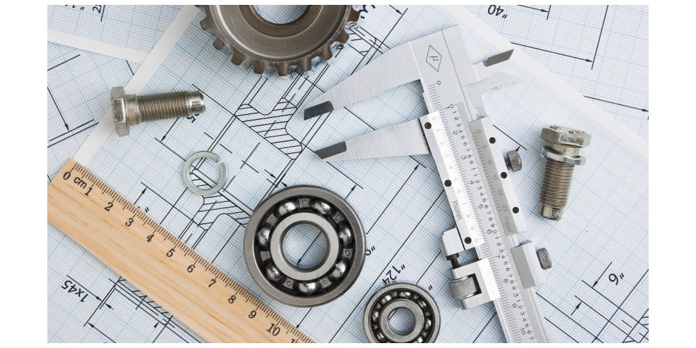
Machined parts are components manufactured using special cutting tools like mills and lathes. They are cut from a large workpiece where materials are removed to create the desired pieces. With time, machined parts have proven to be the most sort after pieces compared to molded or 3D printed parts. Additionally, they are easy to produce and are more cost-friendly. Any design can pass when creating machined parts, but few design limitations exist. In this post, we expound on the specifications for designing machined parts.
Rules for Developing Machined Parts
When DFM or design for manufacturing principles are followed, designing becomes more effortless. These rules vary from one machining process to another, for example, CNC machining and 3D printing. The CNC machining specifications are;
1. The thickness of the wall
Generally, machined parts are formed from materials that don’t experience drastic deformity. They may deform or not, but the percentage is usually very small such that it goes unnoticed. The reason for using such materials is that the parts have thick walls. In processes like injection molding, the deformity is very high if products are designed with thick walls.
Based on their DFM principles, having thin walls is a must. As for machined parts, thin walls are to be avoided as they are difficult to machine. They need to be thick and robust but with particular measurements. Metal and plastic are the primary materials for making these parts. The wall thickness for metal should be 0.8mm minimum and 1.5mm for plastic.
2. Part protrusions
A protrusion is anything above the product surface. Such sections appear in different sizes depending on the machining process used. Usually, they are vital areas of the machined parts, but they can cause more harm than good if too tall. They make the entire production process difficult, similar to having thin walls. Tall protrusions are prone to damage by the vibration produced during machining. Any damage encountered reduces the part accuracy; hence should be avoided. Any desired protrusion height should be four times its width.
3. Size of the parts
Machined parts are made in different sizes, one because of the customer’s request and two because of the machine limitations. There are several CNC machines, each with specific dimensions. The machines are standard, but a manufacturer can use larger devices upon request for customization purposes. For regular machine sizes, the milling machine should produce parts of 400 by 250 by 150mm. The turner machine should have pieces measuring 500mm by 1000mm.
4. Part undercut
Undercuts are parts of a workpiece that cannot be reached using standard cutting devices. They often appear on the piece but avoiding them would be great as the machining time is reduced. Due to their positioning, unique tools like T-shaped tools are needed to facilitate the process. The manufacturer should design the undercut in millimeters to match the required tools. The undercut should have a width between 3 and 40 mm and a depth two times its width.
Last words
The design for manufacturing principles above is essential in the production of machined parts. They suit the CNC machining process meaning you cannot apply them in other manufacturing procedures. The products developed are accurate and precise, and the entire process is quick and easy since the guidelines are already laid out.

